UEFI Firmware Volumes Explained: FV, FFS, HOBs, and Flash Access
A UEFI firmware image is more than a collection of executable files stored in a flash chip. It is a structured binary image containing firmware code, configuration data, recovery components, persistent variables, and other platform-specific information.
Understanding how these pieces fit together is essential when developing BIOS firmware, debugging boot failures, analyzing firmware images, or implementing platform customization.
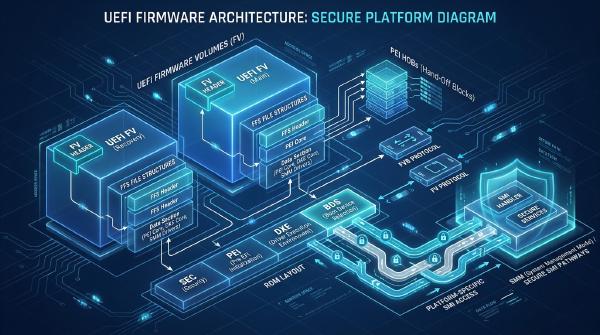
The central abstraction in the UEFI Platform Initialization (PI) architecture is the Firmware Volume (FV). An FV organizes firmware files into a defined binary format. Those files use the Firmware File System (FFS), while the PEI and DXE phases discover and process firmware volumes through standardized interfaces.
This guide examines the relationship between physical firmware devices and logical firmware volumes, the structures that make up an FV and its files, the PEI-to-DXE handoff, and the protocols used to access firmware storage. It also covers NVRAM organization, fault-tolerant updates, and platform-specific SMI mechanisms found in some legacy AMI Aptio implementations.
🧩 1. Firmware Devices, Firmware Volumes, and FFS #
Before examining individual structures, it helps to distinguish three terms that are often used interchangeably: Firmware Device, Firmware Volume, and Firmware File System.
They describe different layers of firmware storage.
1.1 Firmware Device vs. Firmware Volume #
A Firmware Device (FD) is the physical storage repository containing firmware data. SPI NOR Flash is a common example in modern x86 systems.
A Firmware Volume (FV), by contrast, is a logical storage region defined by the PI architecture. It organizes firmware files and associated metadata according to a standardized format.
A single physical flash device can contain several firmware volumes, along with regions that are not formatted as FVs.
| Concept | Description |
|---|---|
| Firmware Device (FD) | Physical nonvolatile storage containing firmware code and data |
| Firmware Volume (FV) | Logical firmware storage region with a defined header and contents |
| Firmware File System (FFS) | Binary format used to organize files inside an FV |
| Firmware File | Individual component identified by a GUID and file-type metadata |
| Firmware File Section | Typed data contained inside an FFS file, such as a PE32 image or compressed section |
For example, a motherboard’s SPI flash may contain:
- Early boot firmware.
- DXE drivers and other UEFI components.
- Recovery firmware.
- Persistent UEFI variables.
- Management Engine or other platform-specific regions.
- OEM configuration and manufacturing data.
Not every region is a Firmware Volume, and not every FV must occupy a separate physical flash device.
This distinction matters when examining a raw firmware image. A region boundary in a flash layout does not automatically indicate the beginning of an FV. The actual format must be identified from its header and surrounding structures.
1.2 Why Firmware Images Contain Multiple Volumes #
Firmware volumes allow different categories of firmware code and data to be organized independently.
A platform might use separate volumes for recovery firmware, PEI modules, DXE drivers, and other components. This makes it easier for firmware components to locate the data they need without relying on a single flat binary layout.
However, there is no universal FV partition map. The number of volumes, their sizes, and their purposes depend on the firmware vendor and motherboard design.
When analyzing a firmware image, identify the actual storage map rather than assuming that every platform follows the same layout.
For a broader explanation of how firmware storage relates to the UEFI boot process, see UEFI BIOS Architecture and Boot Flow.
1.3 Typical NVRAM Organization #
Many AMI Aptio-based firmware implementations reserve part of the flash device for persistent UEFI variables and related metadata.
A representative layout may contain:
| Region | Purpose |
|---|---|
FTW_SPARE |
Spare storage used by the Fault-Tolerant Write mechanism |
FTW_WORKING |
Working metadata for fault-tolerant operations |
EVENT LOG |
Platform-specific firmware event records, when supported |
Variable |
Persistent UEFI variable storage |
These names are common in certain firmware implementations, but they are not mandatory PI architecture requirements.
The actual region sizes and organization depend on the platform. A 64 KiB variable store, for example, is one possible configuration rather than a universal UEFI requirement.
Do not confuse the variable store with the entire NVRAM region or assume that every firmware image uses the same FTW layout.
1.4 Fault-Tolerant Write #
Flash devices impose restrictions on how stored bits can be modified. Depending on the device, programming can change bits in only one direction until the relevant erase block is erased.
This creates a problem when firmware must update persistent data while preserving a recoverable state if power disappears halfway through the operation.
The Fault-Tolerant Write (FTW) mechanism addresses this problem in supported firmware implementations.
At a high level, FTW uses working metadata and spare storage to help recover from interrupted updates. Instead of treating a variable-store modification as an ordinary unrestricted memory write, the firmware follows a controlled process that preserves enough information to complete or recover the operation.
FTW does not make every flash operation failure-proof. Its guarantees depend on the implementation, storage layout, and assumptions made by the firmware update code.
When debugging variable-store corruption, inspect the actual FTW driver and region definitions rather than assuming that every Aptio implementation behaves identically.
🧱 2. Understanding the Firmware Volume Header #
Every standard PI Firmware Volume begins with an FV header. It describes the volume’s length, filesystem format, attributes, checksum, and block organization.
When parsing a raw firmware image, the FV header is one of the most useful landmarks.
2.1 EFI_FIRMWARE_VOLUME_HEADER
#
A typical PI firmware volume header is defined using the following structure:
typedef struct {
    UINT8                  ZeroVector[16];
    EFI_GUID               FileSystemGuid;
    UINT64                 FvLength;
    UINT32                 Signature;
    EFI_FVB_ATTRIBUTES_2   Attributes;
    UINT16                 HeaderLength;
    UINT16                 Checksum;
    UINT16                 ExtHeaderOffset;
    UINT8                  Reserved[1];
    UINT8                  Revision;
    EFI_FV_BLOCK_MAP_ENTRY BlockMap[];
} EFI_FIRMWARE_VOLUME_HEADER;
Each field provides information needed to interpret the volume.
| Field | Purpose |
|---|---|
ZeroVector |
Reserved bytes that are normally zero |
FileSystemGuid |
Identifies the filesystem format used by the volume |
FvLength |
Total length of the firmware volume |
Signature |
Identifies the structure as a firmware volume |
Attributes |
Describes supported volume capabilities and properties |
HeaderLength |
Size of the FV header |
Checksum |
Header integrity checksum |
ExtHeaderOffset |
Offset to an optional extended header |
Revision |
Firmware volume header revision |
BlockMap |
Describes the volume’s erase-block organization |
The FileSystemGuid is particularly useful when analyzing firmware images because it identifies the filesystem format expected inside the volume.
The FvLength field provides the volume’s total size, while the block map describes how its storage is divided into blocks.
2.2 Header Validation #
Finding a possible FV signature is not enough to establish that a region contains a valid firmware volume.
A parser should validate several fields:
- Check that the signature matches the expected FV signature.
- Confirm that
FvLengthis large enough to contain the header. - Verify that the volume does not extend beyond the available image data.
- Check that
HeaderLengthis valid and within the volume boundary. - Validate the header checksum.
- Parse the block map and confirm that its entries are consistent with the volume length.
The checksum is calculated according to the PI specification. A parser should not assume that an arbitrary sequence of bytes following a matching signature represents a valid FV.
Malformed lengths or block-map entries can cause an image parser to read outside the intended region, so bounds checking is essential.
2.3 Extended Headers and Revision Differences #
The optional extended header provides additional information about a firmware volume.
Its location is described by ExtHeaderOffset. A value of zero indicates that no extended header is present.
Firmware engineers should also pay attention to differences between PI specification revisions and older EFI Framework or vendor-specific implementations.
Some older Aptio codebases use legacy structure definitions that differ from current PI headers. When working with an existing firmware source tree, use the definitions supplied by that implementation and compare them with the applicable specification revision.
Mixing structure definitions from different generations can produce incorrect offsets and cause otherwise valid firmware images to be parsed incorrectly.
📦 3. FFS: How Firmware Files Are Organized #
A Firmware Volume provides the container. The Firmware File System organizes the individual firmware components stored inside it.
An FFS file has a GUID-based identity, a file type, attributes, a size, and a state. Its contents can include one or more sections.
Common file types include:
- PEI core and PEIM modules.
- DXE drivers.
- UEFI applications.
- Firmware volume images.
- Freeform or raw data files.
- Other PI-defined firmware components.
3.1 The FFS File Header #
A conventional FFS file header contains fields similar to the following:
typedef struct {
    EFI_GUID                Name;
    EFI_FFS_INTEGRITY_CHECK IntegrityCheck;
    EFI_FV_FILETYPE         Type;
    EFI_FFS_FILE_ATTRIBUTES Attributes;
    UINT8                   Size[3];
    EFI_FFS_FILE_STATE      State;
} EFI_FFS_FILE_HEADER;
The GUID in Name identifies the file. The Type field indicates what kind of firmware component it contains, while Attributes controls how the file should be interpreted.
The three-byte Size field stores the file’s total size for ordinary FFS files.
The State field is also significant. It records the file’s lifecycle state, including whether the file header and data are valid or whether the file has been marked for update or deletion.
A raw binary parser must interpret this field according to the FFS state rules rather than assuming that every file-like structure in the image is active.
3.2 Large FFS Files #
The standard FFS header uses a three-byte size field, which limits the size that can be represented directly.
For larger files, the format supports an extended header:
typedef struct {
    EFI_GUID                Name;
    EFI_FFS_INTEGRITY_CHECK IntegrityCheck;
    EFI_FV_FILETYPE         Type;
    EFI_FFS_FILE_ATTRIBUTES Attributes;
    UINT8                   Size[3];
    EFI_FFS_FILE_STATE      State;
    UINT64                  ExtendedSize;
} EFI_FFS_FILE_HEADER2;
When the FFS_ATTRIB_LARGE_FILE attribute is set, the extended header is used and the ordinary Size field must be zero.
The parser must therefore inspect the file attributes before deciding how to calculate the header size and locate the file’s contents.
Assuming every FFS file has the same header size is a common source of parsing errors.
3.3 File Integrity and State #
FFS headers contain integrity information used to validate the file header and, depending on the file attributes, its data.
The IntegrityCheck field contains the relevant integrity values. The FFS_ATTRIB_CHECKSUM attribute determines whether the file-data checksum is used.
The State field tracks the file’s status within the firmware volume.
These details matter when examining modified or partially updated firmware images. A file may still appear in the raw byte stream even though its state indicates that it is no longer considered a valid active file.
A reliable parser must account for:
- Header integrity.
- Optional data checksums.
- File attributes.
- File state.
- Alignment requirements.
- Extended-size handling.
It should also distinguish standard PI behavior from legacy or vendor-specific conventions. Older firmware implementations may contain structures that are not part of every standard FFS format.
🔄 4. Firmware Volume HOBs and the PEI-to-DXE Handoff #
Firmware volumes are not useful only as static containers. The firmware must also discover their locations during boot and make relevant information available to later execution phases.
This is where the PEI-to-DXE handoff becomes important.
During the Pre-EFI Initialization (PEI) phase, firmware initializes enough hardware and memory to prepare the platform for DXE execution.
One of the mechanisms used to communicate information between phases is the Hand-Off Block (HOB) list.
4.1 What Is a Firmware Volume HOB? #
A Firmware Volume HOB describes a firmware volume available to the next phase of initialization.
It allows PEI components to communicate information about discovered firmware volumes without requiring DXE to repeat the same discovery process from scratch.
A typical sequence looks like this:
- PEI firmware discovers or loads a firmware volume.
- PEI creates the corresponding firmware volume HOB.
- The HOB is added to the HOB list.
- DXE receives the HOB list during initialization.
- DXE uses the information to locate and process available firmware volumes.
This handoff is particularly useful when firmware volumes are loaded from different sources or placed at different memory addresses during initialization.
4.2 Why the HOB List Matters #
The HOB list carries information gathered during PEI initialization into the DXE environment.
It can describe resources and firmware components discovered before DXE begins, including:
- Memory resource information.
- Memory allocations.
- Firmware volume locations.
- CPU and platform information.
- Other initialization data defined by the PI architecture.
The firmware volume HOB is therefore one part of a broader mechanism for transferring platform initialization information.
When debugging a DXE driver that cannot locate a required firmware component, checking the HOB list can help determine whether the volume was discovered and reported correctly during PEI.
4.3 Avoid Confusing Physical and Memory Addresses #
A firmware volume’s physical storage location and its address in memory are not necessarily the same.
A volume may originate in SPI flash and later be copied, decompressed, or otherwise made available in memory.
Consequently, a parser or firmware driver should not assume that a memory address recorded during initialization is always a direct mapping of the original flash offset.
Understanding the distinction between flash offsets, physical addresses, and virtual addresses is essential when tracing firmware-volume discovery across PEI and DXE.
🔐 5. Firmware Volume Access: FVB and the Firmware Volume Protocol #
UEFI provides different interfaces for accessing firmware storage.
Two important abstractions are the Firmware Volume Block (FVB) protocol and the Firmware Volume Protocol.
They operate at different levels.
5.1 Firmware Volume Block Protocol #
The FVB protocol provides relatively low-level access to firmware volume storage.
Its operations include:
- Reading data from a specified block and offset.
- Writing data to a specified block.
- Querying block sizes and block counts.
- Erasing one or more blocks.
- Retrieving firmware volume attributes.
- Setting supported access and protection attributes.
Although the interface accepts byte counts for read and write operations, the underlying flash hardware may impose additional restrictions.
For example, a flash device may require the relevant erase block to be erased before certain data can be programmed. Erasure generally occurs at block granularity rather than at arbitrary byte offsets.
FVB operations must also respect the read, write, and lock attributes supported by the underlying device.
5.2 Firmware Volume Protocol #
The Firmware Volume Protocol provides a higher-level interface for locating and accessing files inside a firmware volume.
Rather than requiring every caller to understand the physical storage layout, it exposes file-oriented operations.
A firmware component can use this interface to locate a file by its GUID and retrieve the relevant data.
The distinction is straightforward:
| Interface | Access Level | Main Responsibility |
|---|---|---|
| FVB Protocol | Block-level | Reads, writes, erases, and queries firmware storage |
| Firmware Volume Protocol | File-level | Locates and reads firmware files within a volume |
A filesystem implementation can use FVB to access the underlying storage and then expose the higher-level Firmware Volume Protocol to other firmware components.
This separation keeps hardware-specific storage operations distinct from the logic used to interpret FFS files.
5.3 Why FVB Is Not a General-Purpose Firmware Editor #
The fact that FVB supports write and erase operations does not mean that firmware developers can safely modify arbitrary bytes in a firmware volume.
A valid update must preserve:
- FV header integrity.
- FFS file structure.
- File alignment.
- File-state rules.
- Block erase constraints.
- Volume attributes and protection policies.
Changing an FFS file without updating the associated integrity information can leave the volume in an invalid state.
Similarly, erasing a block that contains unrelated firmware data can damage multiple components at once.
For this reason, low-level FVB access should be treated as a storage interface, not as a shortcut for editing arbitrary firmware structures.
🧠 6. NVRAM and Firmware Variables #
UEFI variables provide a standardized way for firmware and operating systems to store configuration data that persists across reboots.
Common examples include:
BootOrder: Defines the preferred boot-option order.Boot0000,Boot0001, and related variables: Store individual boot entries.BootNext: Requests a one-time boot option for the next boot.- Secure Boot variables: Store or reference keys and signature databases used by the platform’s image-authentication policy.
The firmware typically stores persistent variables in nonvolatile storage, often within a dedicated flash region.
The variable services provide a logical interface to this data, hiding much of the underlying storage implementation.
6.1 Variable Storage Is Not the Same as an Entire Firmware Volume #
A variable store may occupy only part of a larger firmware storage region.
It should not be confused with the entire SPI flash device or even the entire firmware volume containing it.
Different firmware implementations may use different layouts, variable-store formats, and recovery mechanisms.
When analyzing a firmware image, identify the variable-store boundaries from the actual platform layout and firmware structures.
Do not assume that a variable store always begins at the same offset or has a fixed size.
6.2 Why Variable Updates Need Protection #
Persistent variables are frequently updated during normal system operation.
For example, boot configuration may change when a user modifies the boot order, installs an operating system, or adds a new boot entry.
Because flash storage has erase-block constraints, variable updates require careful management of available space and existing data.
Fault-tolerant mechanisms such as FTW help firmware recover from interrupted updates, but the exact behavior depends on the implementation.
For developers investigating variable corruption, the variable driver, FTW implementation, and physical flash layout should be examined together.
🛠️ 7. Operating-System Access and SMM-Mediated Flash Operations #
Firmware storage is not automatically available for unrestricted modification from an operating system.
On many platforms, flash access is controlled by chipset configuration, hardware protection registers, firmware policy, and platform-specific update mechanisms.
Some systems also use System Management Mode (SMM) to perform selected privileged firmware operations.
7.1 What Happens During an SMI? #
A System Management Interrupt (SMI) transfers execution to an SMM handler.
The processor enters System Management Mode, where platform firmware can perform privileged operations in an isolated execution environment.
Depending on the platform implementation, an SMI handler may process requests related to:
- Power management.
- Thermal management.
- Hardware configuration.
- Firmware updates.
- Platform-specific management functions.
Some legacy AMI Aptio implementations provide OEM-specific SMI commands for flash-related operations.
These commands are not universal UEFI interfaces. Their parameters, port addresses, access rules, and supported operations depend on the firmware implementation.
7.2 Example of a Vendor-Specific SMI Command Table #
A particular implementation may define commands resembling the following:
| Command | Function | Description |
|---|---|---|
0x23 |
SMI_WriteFlash |
Requests a flash write |
0x24 |
SMI_DisableFlash |
Disables a platform-specific write path |
0x25 |
SMI_GetFlashInfo |
Requests flash-device information |
This table describes one reported implementation. It is not a standard command set for AMI Aptio, UEFI, or SMM.
The command number alone does not define the complete interface. An actual handler may require additional parameters, buffer addresses, validation structures, state checks, or authorization conditions.
Before attempting to use such an interface, inspect the SMI handler implementation and confirm the exact calling convention.
7.3 Security Risks of OS-Triggered Flash Writes #
An operating-system-accessible SMI interface that can erase or write firmware storage is a high-privilege mechanism.
If its input validation is incomplete, an attacker or faulty application may be able to request operations that corrupt firmware or bypass intended update controls.
A secure implementation should carefully validate:
- Command identifiers.
- Buffer addresses and lengths.
- Requested flash ranges.
- Firmware update state.
- Caller authorization.
- Image integrity and authenticity.
- Hardware write-protection state.
It should also handle failures safely and restore the intended protection state after an operation.
An SMI interface should never be assumed to provide authentication merely because it executes inside SMM.
For production firmware updates, use the platform vendor’s documented and authenticated update mechanism. Avoid relying on undocumented private SMI commands as a portable way to modify flash.
For a practical look at firmware update precautions and preserving platform-specific flash regions, see Adding a Custom ACPI SSDT to AMI Aptio.
🔍 8. A Practical Workflow for Firmware Image Analysis #
Understanding FV, FFS, HOB, and flash-access structures is most useful when they are applied together.
When examining an unfamiliar firmware image, use a methodical workflow rather than immediately searching for individual drivers or modifying binary data.
8.1 Identify the Firmware Device Layout #
Start by identifying the physical flash layout.
Determine:
- Flash device capacity.
- Firmware region boundaries.
- Platform-specific reserved regions.
- Recovery and main firmware regions.
- Variable-store locations.
Do not assume that the entire binary file is a single firmware volume.
8.2 Locate and Validate Firmware Volumes #
Search for candidate FV headers and validate their fields.
For every candidate, check:
- FV signature.
- Total volume length.
- Header length.
- Header checksum.
- Filesystem GUID.
- Block-map consistency.
Reject candidates with invalid lengths or structures that extend beyond the available image.
8.3 Parse FFS Files and Sections #
Once a valid FV has been identified, parse its FFS files.
Check each file’s:
- GUID.
- Type.
- Attributes.
- Size.
- State.
- Integrity information.
Handle large-file headers correctly and respect the alignment requirements defined by the applicable format.
After identifying a file, inspect its sections to determine whether it contains a PE32 image, a compressed payload, raw data, or another supported section type.
8.4 Trace Firmware Volume Discovery #
If the task involves runtime firmware behavior rather than static image analysis, trace how PEI discovers and reports firmware volumes.
Inspect the relevant HOB creation and consumption paths.
Then follow the DXE initialization process to determine how firmware components locate and access the volumes.
This helps distinguish a malformed firmware image from a failure in the firmware-volume discovery process.
8.5 Inspect Flash Protection Before Any Update #
Before performing a write or erase operation, identify the protection mechanisms used by the platform.
Depending on the system, these may include:
- Chipset flash protection registers.
- Firmware-region access controls.
- SPI flash status-register protection.
- Firmware-volume attributes.
- Platform-specific SMM update policies.
- Authenticated update requirements.
Do not assume that a successful read means the same region is writable.
For production systems, preserve a verified backup and use the documented update process. Confirm that a recovery method is available before making changes to firmware storage.
⚠️ 9. Common Firmware Analysis Mistakes #
Several recurring mistakes can make firmware parsing and debugging much harder than necessary.
| Mistake | Why It Causes Problems | Better Approach |
|---|---|---|
| Treating an FD as one FV | Physical storage can contain multiple volumes and non-FV regions | Identify the actual flash layout first |
| Assuming every FV has the same size | Volume size depends on the platform layout | Read and validate FvLength |
| Using one FFS header definition for every file | Large files use an extended header | Inspect attributes before parsing the size |
| Ignoring FFS state | Deleted or invalid files may remain in the binary image | Interpret the state field according to the FFS rules |
| Treating flash offsets as memory addresses | Firmware volumes can be copied or relocated | Track physical and memory addresses separately |
| Assuming FVB permits arbitrary writes | Flash has erase-block and protection constraints | Respect the underlying storage rules |
| Treating private SMI commands as standard UEFI APIs | SMI command formats are platform-specific | Inspect the actual handler and its validation logic |
| Assuming FTW prevents every update failure | Recovery guarantees depend on implementation details | Review the FTW driver and storage layout |
These checks are useful whether the goal is building a firmware parser, debugging a DXE driver, or investigating a failed BIOS update.
📚 10. Specifications and Implementation References #
When working with firmware structures, the relevant specification and source-code revision matter.
Useful references include:
- UEFI Platform Initialization Specification: Defines the firmware-volume, FFS, HOB, and related PI architecture structures.
- UEFI Specification: Defines UEFI services, variables, protocols, and the broader firmware execution environment.
- EDK II source code: Provides a widely used implementation of UEFI and PI interfaces.
- Platform vendor documentation: Describes chipset-specific flash layouts, protection registers, and update procedures.
- OEM firmware source trees: May contain implementation-specific extensions and legacy compatibility code.
For low-level development, compare the structures in the target firmware source tree with the applicable PI specification revision. This is especially important when working with older Aptio implementations that may use legacy definitions or vendor extensions.
A structure that looks familiar is not necessarily identical across every firmware generation.