AFDX (ARINC 664 Part 7) Deep Dive: Determinism, Redundancy, and Frame Architecture
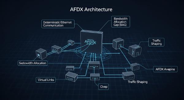
In the previous article, we explored the deterministic foundations of AFDX and examined the three core pillars that enable predictable avionics networking: Virtual Links (VLs), Bandwidth Allocation Gap (BAG), and Traffic Shaping.
This article continues the discussion by diving deeper into the mechanisms that guarantee reliability and determinism in real-world avionics deployments. We will examine jitter constraints, redundancy management, sequence number handling, skew timing, communication ports, Sub-VLs, and AFDX frame structures from both theoretical and implementation perspectives.
✈️ Maximum Admissible Jitter #
At the output of the End System scheduler, frames associated with a given Virtual Link do not always leave the system at the exact ideal BAG boundary. Instead, transmission timing fluctuates within a tightly bounded interval known as the Maximum Admissible Jitter.
This bounded variation is caused by:
- Scheduler implementation precision
- Physical layer transmission overhead
- Token bucket waiting delays
- Internal buffering latency
Although timing fluctuates slightly, AFDX ensures that the deviation always remains within deterministic limits.
Technical Constraints #
AFDX explicitly defines strict jitter boundaries:
- Absolute Maximum Jitter: 500 μs
- Typical Minimum Physical Jitter: ~40 μs
The lower-bound jitter mainly originates from Ethernet transmission overhead, including:
- 12-byte Inter-Frame Gap (IFG)
- 7-byte Preamble
- 1-byte Start Frame Delimiter (SFD)
Together, these contribute a fixed 20-byte transmission overhead per Ethernet frame.
Relationship Between Jitter and Frame Size #
Jitter is also influenced by:
- Maximum VL frame length (Lmax)
- Link bandwidth (Nbw)
Longer frames naturally occupy the physical medium for longer durations, increasing transmission window variability.
Systems with:
- fewer VLs
- shorter frames
- lighter scheduling complexity
typically experience substantially lower jitter values.
The 500 μs limit exists specifically to guarantee that even under worst-case traffic conditions, deterministic latency analysis remains mathematically tractable.
📡 Maximum Usable Bandwidth #
The maximum bandwidth available to a Virtual Link is determined entirely by:
- BAG
- Maximum frame size (Lmax)
The calculation formula is:
BWmax = Lmax / BAG
For example:
- BAG = 8 ms
- Lmax = 1518 bytes
Then:
BWmax ≈ 1518 / 0.008 ≈ 189.75 KB/s
Why This Matters #
By carefully configuring BAG and Lmax values, system integrators ensure:
- Total VL bandwidth remains below physical link capacity
- Congestion never becomes permanent
- Worst-case queuing latency remains bounded
This forms the mathematical basis for deterministic network analysis.
🔁 Redundancy Management #
AFDX achieves fault tolerance using dual physically independent Ethernet networks:
- Network A
- Network B
Each End System contains two Ethernet interfaces and simultaneously transmits identical frames over both networks.
This architecture guarantees communication continuity even if one network path fails entirely.
First Valid Wins #
The receiving End System implements a redundancy management mechanism known as:
First Valid Wins
The receiver monitors both redundant networks simultaneously.
When a frame:
- arrives first
- passes integrity validation
- contains an acceptable Sequence Number
it is immediately delivered upward.
Any later duplicate frame carrying the same Sequence Number is discarded.
This mechanism minimizes latency while preserving redundancy.
🔢 Sequence Number Mechanism #
Every AFDX frame contains an 8-bit Sequence Number (SN).
Valid range:
- 0 to 255
Increment Rules #
For each Virtual Link:
- Sequence numbers increment by one
- After 255, the value wraps back to 1
- SN = 0 is reserved for post-reset initialization frames
Receiver Validation Window #
The receiver validates incoming Sequence Numbers using a moving acceptance window:
[PSN + 1, PSN + 2]
Where:
- PSN = Previously accepted Sequence Number
This design intentionally tolerates single-frame loss without interrupting communication continuity.
Example #
If:
PSN = 254
Then the valid window becomes:
- 255
- 1
The mechanism fully supports wrap-around behavior.
⏱️ Maximum Skew Time (SkewMax) #
Because Network A and Network B may contain different routing paths and switch cascades, redundant frames rarely arrive simultaneously.
AFDX defines a configurable timing parameter called:
SkewMax
This represents the maximum allowable arrival-time difference between two redundant frames.
Purpose #
SkewMax prevents the receiver from waiting indefinitely for a missing redundant copy.
If:
- Frame A arrives
- Frame B does not arrive within SkewMax
then the receiver stops waiting and continues normal processing.
Without this mechanism, a single lost redundant frame could stall all future traffic processing.
🔮 Integrity Check Behavior #
AFDX integrity checking verifies:
- Sequence Number continuity
- Frame validity
- Redundancy consistency
Several important edge cases exist.
Lost Frame Recovery #
If:
- A4 is lost
- B4 arrives correctly
then communication continues normally.
Late Duplicate #
If:
- A3 already advanced the receive window
- B2 arrives later
then B2 becomes invalid and is discarded.
Corrupted Sequence Numbers #
Unexpected jumps such as:
B99
are rejected immediately as integrity failures.
🧩 Communication Ports #
AFDX provides communication services to application partitions through two primary port types.
📥 Sampling Ports #
Sampling ports are designed for periodic real-time data.
Characteristics:
- Only the latest value is stored
- Multiple applications may read the same data
- Ideal for sensor updates and control parameters
Limitations #
Sampling messages:
- cannot use IP fragmentation
- must fit inside a single AFDX frame
Each port also maintains a Freshness Indicator to show whether data has been updated since the last read.
📬 Queuing Ports #
Queuing ports are designed for larger or non-periodic data transfers.
Characteristics include:
- FIFO buffering
- IP fragmentation support
- Complete message delivery guarantees
Maximum supported payload size:
- Up to 8 KB
Typical use cases include:
- file transfer
- map uploads
- maintenance data
Error Handling #
If FIFO overflow occurs:
- transmit errors are reported
- receive errors are reported
This allows applications to detect communication failures explicitly.
🔀 Sub-Virtual Links (Sub-VLs) #
AFDX optionally supports:
Sub-Virtual Links (Sub-VLs)
Sub-VLs improve bandwidth fairness within a single VL.
Why Sub-VLs Exist #
Without Sub-VLs:
- large queuing messages
- fragmented transfers
could monopolize BAG cycles and delay short real-time messages.
Scheduling Method #
Each Sub-VL maintains:
- an independent FIFO queue
The main VL scheduler services Sub-VLs using:
Round-Robin scheduling
During each BAG cycle:
- one frame (or fragment) is transmitted
- polling pauses until the next BAG
- the next cycle resumes from the next Sub-VL
This prevents large fragmented transfers from starving smaller real-time traffic.
Importantly, determinism remains intact because the parent VL still obeys:
- BAG rules
- token bucket constraints
🧱 AFDX Frame Structure #
AFDX is built on top of standard IPv4 Ethernet networking.
The protocol stack structure is:
- Ethernet Header
- IP Header
- UDP Header
- AFDX Payload
AFDX Payload Layout #
The payload contains:
- 1-byte Sequence Number
- Application data
Because of the Sequence Number field:
- Maximum IPv4 payload decreases from 1500 bytes to 1499 bytes
Larger data therefore requires IP fragmentation.
🌐 Communication Identification #
AFDX uniquely identifies communication flows using a 5-tuple:
- Source UDP Port
- Source IP Address
- Destination MAC Address (including VL ID)
- Destination IP Address
- Destination UDP Port
This mechanism allows:
- multiple VLs
- multiple application flows
to coexist between the same End Systems.
🛡️ Determinism Through Coordinated Constraints #
AFDX achieves deterministic avionics networking not through a single mechanism, but through the careful coordination of multiple tightly controlled constraints:
- Virtual Links isolate traffic logically
- BAG regulates transmission timing
- Traffic Shaping smooths burst behavior
- Redundancy Management guarantees reliability
- Sequence Numbers preserve ordering
- SkewMax prevents indefinite waiting
- Sub-VLs improve fairness without sacrificing determinism
Together, these mechanisms transform conventional Ethernet into a mathematically analyzable, highly reliable avionics communication system suitable for safety-critical aerospace environments.
Even today, AFDX remains one of the most sophisticated deterministic Ethernet architectures ever deployed in commercial aviation systems.